

| CERN -> ATLAS -> TU Vienna | ||
   |
High-Density Digital Links |  |
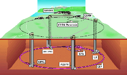
CERN1, the European Laboratory for Particle Physics, is a very special environment itself - see Figure 1.1. So are the particle accelerators and detectors which will be described in this introduction to give an overview about the system.
 |
| CERN |
CERN - the Conseil Européen pour la Recherche Nucléaire [1] - is the world's largest scientific laboratory for high-energy physics. More than 7,000 scientists from laboratories and universities all over the world use its facilities near the city of Geneva to study the constituents of matter and the nature of fundamental forces.
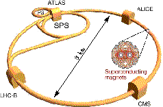
For this purpose, physicists investigate the reactions among colliding elementary particles. Huge machines - see Figure 1.2 - accelerate these particles to velocities close to the speed of light and collide them with high energies, where they are converted into new particles. The Standard Model derived from these investigations formulates a coherent theory, but it does not yet answer everything.
| Higgs Particle |
One of the unsolved miracles is the origin of mass. It could be solved by the so called Higgs mechanism. This mechanism suggests that particles acquire mass by interacting with a force field - the Higgs field. Raising the impact energy of particle collisions well above 1 TeV, could prove the theory by the discovery of an associated Higgs Particle.
| LHC |
To provide an energy of more than 1 TeV, a new particle accelerator - called LHC2 or Large Hadron Collider - will replace the current accelerator - called the LEP or Large Electron Positron collider. This machine will allow to address the problem concerning the Higgs particle and to achieve further insights - see Figure 1.2.
Like the LEP in Figure 1.1, the LCH in Figure 1.2 will be a circular accelerator, placed in a ring tunnel of a perimeter of about 27 km at a depth of approximately 100 m underground. LHC will collide proton beams with energies around 14 TeV at interaction rates of 40 MHz or beams of heavy ions such as lead with a total collision energy in excess of 1,250 TeV.
The particle interactions will happen in discrete locations surrounded by four new particle detectors. ALICE (A Large Ion Collider Experiment) and LHCb (Large Hadron Collider Beauty) are two smaller detectors which will study heavy ions, CP violations, and rare B decays - see Appendix A. ATLAS (A Toroidal LHC ApparatuS) and CMS (Compact Muon Solenoid) are two big experiments which will investigate proton-proton interactions. The four experiments are built in different technologies to succeed in their own specific tasks.
 |
| ATLAS |
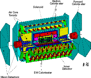
ATLAS3 (A Toroidal LHC ApparatuS) is a particle detector of the size of a five-story building 100 m underground. Its cylindrical shape has a diameter of 22 m and a length of 45 m. Through the center of the detector runs the beam pipe which carries the particle beams. Particles travelling in opposite directions through this pipe collide in the middle of the detector and produce new particles. These are not evident until they either interact with the detector in a measurable way or decay into detectable particles.
For this purpose, the detector consists of an inner tracker (the Inner Detector) which registers the tracks of the charged particles, several calorimeters (the electromagnetic - EM - calorimeter, the Hadron Calorimeter, and the Forward Calorimeter) which measure the energy of the particles, a muon spectrometer (the Muon Detectors) which identifies and measures muons, and a pair of magnet systems (the Solenoid and the Air-Core Toroids) which bends the tracks of the particles to identify them - see Figure 1.3.
 |
| Inner Detector |
The inner region of the detector - the Inner Detector4 - is responsible for the tracking of the path of a charged particle. It is filled with finely subdivided sensing elements which produce a signal when a charged particle hits them. From these signals and the known detector locations, charged particle trajectories can be reconstructed. A solenoidal magnet creates a magnetic field of two Tesla parallel to the beam axis. The path of a charged particle curves in this magnetic field and allows determination of the momentum and the sign of the charge from the radius and the direction of the curvature.
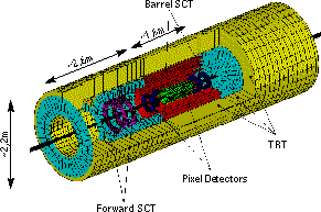
The Inner Detector of ATLAS consists of three different parts: the Pixel detector, the Semiconductor Tracker (SCT), and the Transition-Radiation Tracker (TRT) - see Figure 1.4.
The Pixel detector5 is closest to the collision point. It consists of about 140 million detecting elements: thin layers of silicon subdivided into rectangular regions - the pixels - with resolutions of 10 um in radial and azimuthal direction and 50 um in axial direction.
The SCT6 is built of layers of silicon strip detectors. Each strip detector has two sets of layers of silicon subdivided into narrow strips about 80 um wide and several centimeters long which are running at an angle relative to each other. The intersection of those strips provides a three-dimensional position measurement with a resolution of about 20 um in radial and azimuthal direction and 700 um in axial direction.
 |
The TRT7 is a collection of gas drift detectors, which consist of metal-plated kapton tubes - the straws - with thin wires running through their centers. The tubes are filled with a special Xe-gas mixture and have high voltage maintained between the wire (anode) and the tube wall (cathode).
When a charged particle traverses a tube, it ionizes the gas. The arisen electrons drift at a constant speed towards the wire. This produces an electrical signal which indicates which tube was traversed. Measuring its arrival time relative to the beam collision indicates how far from the wire the particle passed. In the center section the tubes run parallel to the beam pipe. In the two end sections the tubes are positioned radially.
Transition radiation - therefore Transition Radiation Tracker - consists of X-rays generated when electrons moving at speeds close to the speed of light traverse interfaces between materials with different dielectric constant. The transition X-rays interact at a single point in the gas of the straw tubes and produce much larger pulses than traversing charged particles. The detection of such large pulses helps identifying the particle as an electron.
| Calorimeters |
Calorimeters determine the total energy of traversing particles. The electromagnetic calorimeter8 surround the Inner Detector; it measures the energy of electrons, positrons, and photons. The Hadronic calorimeter9 - further outside - measures the energy of hadrons, which are strongly interacting particles like protons, neutrons, pions, and other mesons.
An electromagnetic calorimeter absorbs the energy of all traversing electrons and photons and produces signals proportional to those energies. It is finely subdivided to measure the directional dependence of the electromagnetic energy. In ATLAS the calorimeter consists of thin lead plates - each about 1.5 mm thick. The lead plates are immersed in a bath of liquid argon as a sensing device. Hence the electromagnetic calorimeter is also called the LAr Calorimeter. When high-energy photons or electrons traverse the lead, they produce an electron shower which is proportional to the incident energy. The liquid-argon gaps of about 4 mm between the plates are subjected to a large electric field. When one of the shower electrons or positrons gets into the argon, it produces a trail of electron-ion pairs along its path. The electric field causes the ionization electrons to drift to the positive side. They move faster than the ions and their motion produces an electric current in an external circuit connected to the calorimeter.
The Hadronic Calorimeters surround the electromagnetic calorimeter. It absorbs and measures the energy of hadrons, including protons and neutrons, pions and kaons, whereas electrons and photons are stopped before reaching this sphere. In ATLAS the hadronic calorimeters consist of steel absorbers separated by tiles of scintillating plastic. Hence it is also called the Tile Calorimeter. Interactions of high- energy hadrons in the plates transform the incident energy into a hadronic shower of many low-energy protons and neutrons and other hadrons. This shower, when traversing the scintillating tiles, causes them to emit light in an amount proportional to the incident energy.
| Muon Spectrometer |
Muons are the only charged particles
which are able to travel through the whole calorimeter material and reach
the outer layer. The muon spectrometer10
surrounds the calorimeter and measures muon paths to determine their momenta
with high precision. It consists of thousands of charged particle sensors
placed in the magnetic field produced by large superconducting toroidal
coils. The sensors are similar to the straws described for the Inner Detector
but with larger tube diameters of a couple of centimeters.
| February 9, 2000 - Martin Mandl | Copyright © CERN 2000 |